How to make your own miniature
By Lassi Warsta, Heidi Salo and Simo Hiltunen JUN 16, 2017
We had been discussing for a while about making our own miniature (mini), a small figurine that could be used in tabletop games (Figure 1). One of us was involved in the gaming scene and knew that there were plans to organize a tabletop Fantasy Football tournament in the Helsinki area in spring 2017. Tournaments sometimes give custom minis to the participants as a welcome gift and we thought that this was a perfect opportunity to try out 3D printing in a real production environment. The event was named after a well-known Finnish Fantasy Football couch who happens to bear an uncanny resemblance to one of the star player characters in the game. It was then pretty straightforward to come up with an idea of a mash-up of the coach and the star player, which would then also be usable in the game. Only thing left to get the project started was to get the organizers excited about the idea and luckily they were onboard almost immediately. Although the tournament already took place in May, the mini can still be bought from Tursas Miniatures if you missed the tournament.
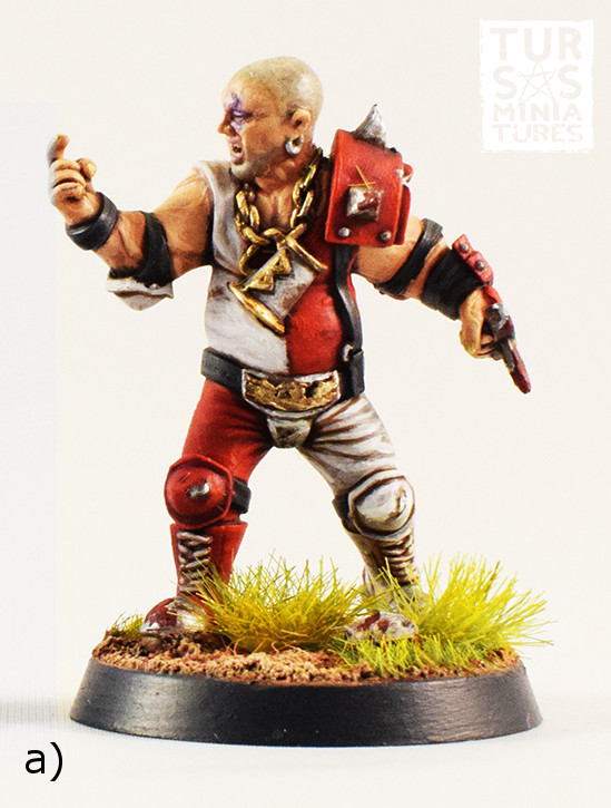
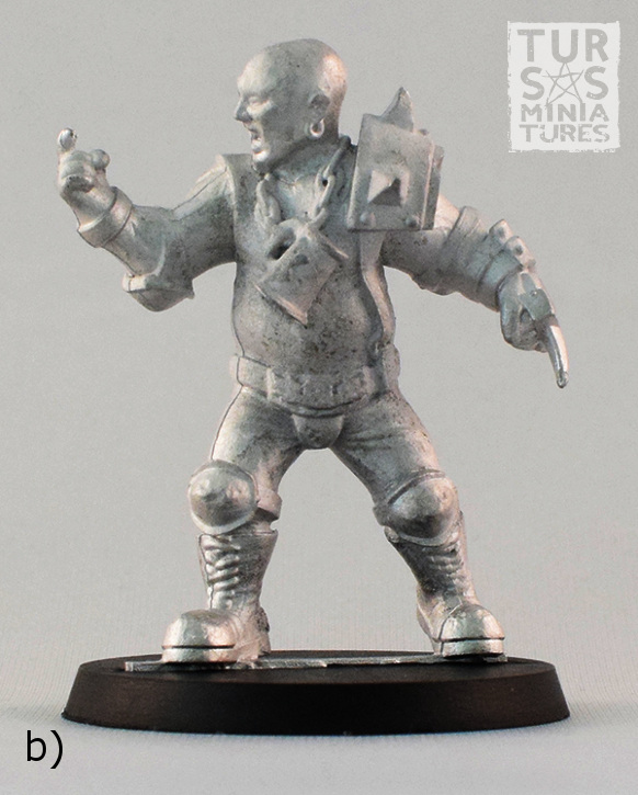
Figure 1. a) A painted resin version of the miniature and b) an unpainted white metal cast.
The new scale of the Fantasy Football minis is 32 mm (the distance from the sole of the foot to the eye level for a 180 cm tall person) versus the old 28 mm scale. Even when adopting the new slightly larger scale, the previously tested fused filament fabrication (FFF) based 3D printers would have experienced problems in reproducing objects of such a fine scale. Or at least we would have had to use special narrow nozzles for the printers. Fortunately, the Iso Omena library in Espoo had just acquired several new Formlabs Form 2 3D printers touted at the time to be the best desktop printers of its kind. As we had not tried stereolithography based printers yet this was a perfect opportunity to test them in a challenging project. As the objective was to prepare a relatively large number of copies of the mini for the tournament organizers, printing them all with the library devices was not considered feasible. Also, there are restrictions concerning the printers (for example time limits) and rules against commercial use. Instead, we planned to print resin master figures with the printers and then order white metal casts of the figure from a professional service (Figure 1b). Learning to do metal casting would have been a bit too large endeavour at this point.
The design phase was started by collecting images of all the previous iterations of the star player character in the game and finding photographs of the coach and saving them into a document. We then added written descriptions of ideas which might fit the new figure including poses, expressions, clothes, armour and accessories in an unsorted list. Based on the list and available reference images we wrote down a basic description of the character. Concept drawings of the figure were then made with the character in the selected pose where he is shaking his right index finger at an opponent while his other hand with a knuckle duster is hidden behind his back (Figure 2a). Additional drawings were made in which the character is in T pose (Figure 2b) for 3D modelling purposes. The pose of the character (Figure 2a) is flatter in the y-direction, to facilitate an easier fit between rubber disks in the mould making process. A more complex pose is possible but it might require that character is cast in several pieces. The pose was slightly adjusted during the modelling phase by rotating the right hand and curling the finger as if the character is asking the opponent to come to him. Also the expression was changed from angry to a wry grin.
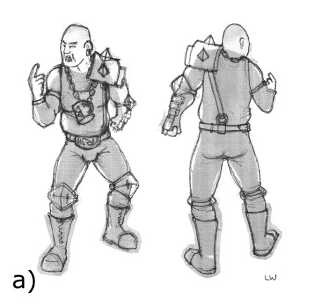
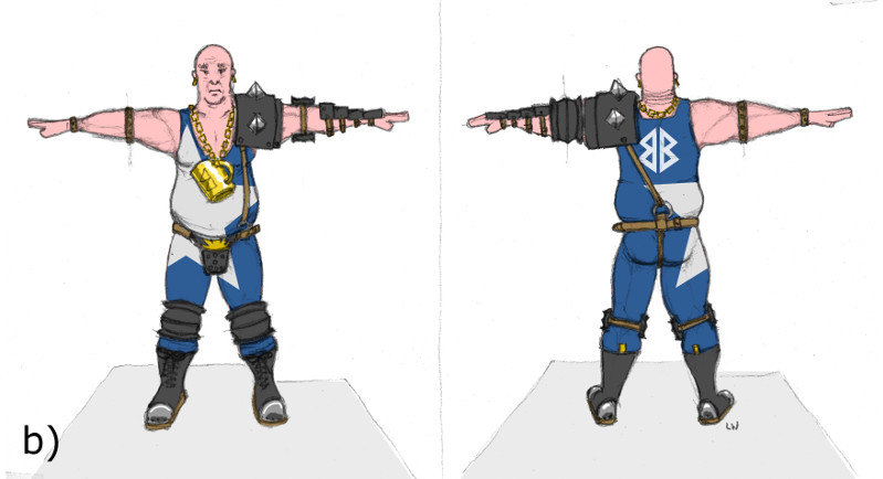
Figure 2. a) Conceptual drawing of the character and b) drawing of the character in T pose used as a reference for 3D modelling.
The character was modelled in the Blender 3D program using similar approaches applied in previous projects (Figure 3). The template drawings were set as a background for front and back views and scaled to the right size. A low polygon version of the character was first modelled according to the plans. Armour pieces were modelled as separate pieces. It was quickly obvious that proportions that worked on paper did not work for the printed model because real world proportions are much too thin for minis. Limbs were remodelled thicker and head, hands and feet were scaled larger. After a test 3D print details such as leather straps, spike in the left hand and armour pieces were further enlarged and made thicker. Before rigging, hands of the model and forearms were rotated 90° to a vertical position for nicer deformations in the forearm after the character was posed. Also, the characters arms were lowered to A pose (arms in 45° angle) because the T position was causing problematic deformations in the arm pit area.
The Riggify system in Blender was used to create a skeleton and skin the character automatically. A Riggify metarig was first added to the project and scaled to the proportions of the character. All the parts of the model were parented to the metarig and then the Riggify build system was activated. The Rigify system then created a rig according to the metarig proportions and attached the meshes to it with Armature modifiers. Some manual weight painting was required after this. The deformation bones responsible for moving the meshes are hidden and the layer has to be exposed before weight painting is possible. Multiresolution modifiers were set above the skin modifiers for further detail sculpting. This kept the rig usable during the whole modelling process as it was only moving the low resolution base mesh even though the final mesh was composed of millions of polygons. Details such as facial expression, scarred left eye, dents and wear in armour, clothing folds and other details were modelled with sculpting tools (Figure 3). The base where the figure stands was modelled separately with polygonal tools.
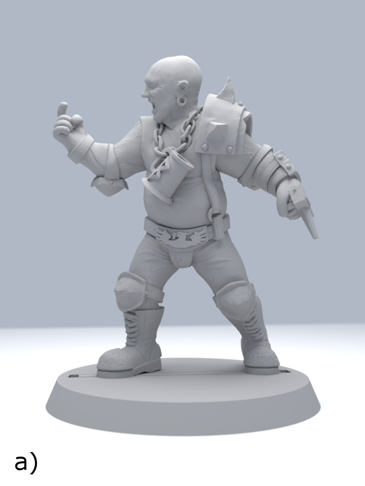
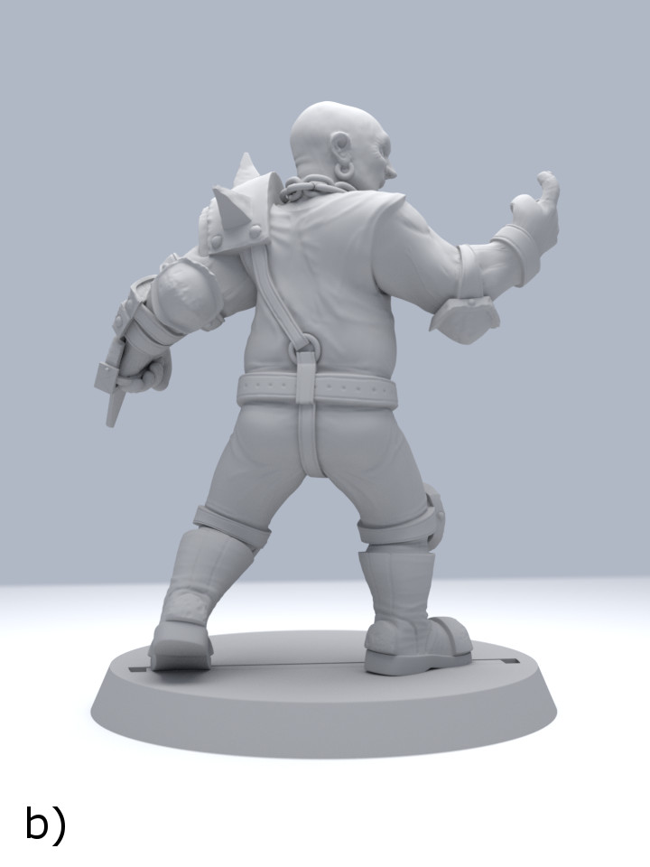
Figure 3. Rendered images of the character from a) front and b) back.
The finished figure was printed with the Formlabs Form 2 stereolithography based printers (3991.79 € Incl. VAT) provided by the Iso Omena Library (Figure 4a). There is currently no fee in using the printers in the library but children under 18 cannot use the printers without an accompanying adult due to safety cautions caused by the printing material itself and the chemical cleaning agent (isopropanol) used in the process. Also the devices were located in a room with other power tools with similar restrictions. The staff wishes that the printers are used in well justified projects because of the relatively high cost of the resin compared to PLA. The printer uses a laser to cure liquid photopolymer resin layer by layer on a vertically moving tray. The model is build upside down and the build plate moves upwards as the printing progresses. The total printing volume is 145×145×175 mm3. The printer can print 0.025, 0.050, 0.100 mm layer depths. Minimum feature size on the X–Y plane is about 0.150 mm, which is only 0.010 mm larger than its 0.140 mm laser (FormLabs, 2016). Currently five categories of materials are available for the printer including Standard, Engineering, Jewelry, Dentistry and Form X. Materials installed in the library were Standard Clear (163.35 € per L Incl. VAT) and Engineering Tough (204.49 € per L Incl. VAT), and we ended printing the mini with the Clear material because there was no obvious benefit in using the more expensive Tough material.
The printer instruction file for the Form 2 printer is created in PreForm software (Figure 4b) and the file is passed to the printer via USB cable or wirelessly. Online printers and the printing process can be followed remotely through a web service. The position of the figure was first set face down in a 45° angle by the software (optimal printing option) and the mini was suspended in air by supporting structures. We ended up turning the front side up in order to keep the front clear of supports. The support structures included a relatively thick base used to attach the mini to the printing tray. The base was essential because force had to be applied to extract the printed mini from the metal tray with a tool resembling spatula. It was possible to modify the support structure options like thickness of the base, density of the support ticks and height above the base in PreForm. Minimizing the support structures reduced printing time by mere minutes and we ended using the default setup for the supports. After the printing process was finished the tray moved up and it was possible to open the transparent orange plastic casing and remove the tray.
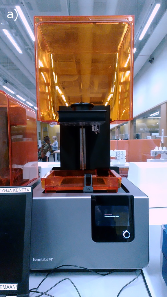
Figure 4. a) Photograph of the FormLabs Form 2 printer and b) printing setup in PreForm software. The actual mini is drawn with blue color and the supports are the white structures. It is possible to adjust the thickness of the base (1), the density of the support pillars (2) and the height above the base (3).
The print was then extracted from the tray and dropped into a vat filled with isopropanol to clean liquid resin from the mini. This stage was pretty messy and rubber gloves should be worn to prevent resin from touching skin or clothes. After 20 min in the isopropanol bath, the mini was rinsed with water and put into a UV oven. The UVA radiation (wave lengths 365, 385 and 405 nm) finishes the resin curing process and makes the print more durable (Zguris, FormLabs WhitePaper). Putting the mini out in the sun is also an option but in Finland UV levels are very low in the winter. The color of the print is affected by the UV curing process. In the UV oven the color of the clear material is a bit yellowish compared to print that is cured in daylight. The curing times for the print vary from minutes to days depending on if one uses UV oven or daylight options. We found that approximately 20 min in the UV oven was sufficient to cure the print after a proper isopropanol treatment. The Engineering Tough material remains flexible before UV exposure but the printed Clear material is rigid after cured by the laser. After the UV oven treatment the support structures were removed with pliers and the mini was sanded clean of support rod bits.
Printing of the three master versions of the figure with 0.025 mm layer depth took approximately 5–6 h. Calculated printing time estimated by PreForm software was 4.75 h. Each figure and supporting structures consumed on average 6 ml of the resin, and the materials costs per figure were approximately 0.5 €. Interesting thing was that when the number of figures printed simultaneously was increased, the printing time did not increase linearly (1 figure: 3.67 h, 2 figures: 4.17 h). It appeared that a large fraction of the time was consumed when the printer tray moved upwards and at the same time the resin in the lower tank was stirred using a paddle with horizontal motions. We also tested printing the figure with 0.050 and 0.100 mm layer depths which took 2.25 h and 1.6 h in order to compare printing times and quality between the resolutions (Figure 5). The printing time increased by 0.6 factor when the layer depth was increased from 0.025 mm to 0.050 mm and by 0.7 when depth was increased from 0.050 to 0.100 mm. The reduced printing quality was clearly seen between the 0.050 mm and 0.100 mm layer thicknesses (Figure 5a and 5b). The small details (belt, face, text on the stand) were slightly blurry and the layers were clearly visible in the head and upper body. There were no clear visible differences between the prints produced with 0.050 and 0.025 mm layer thicknesses.
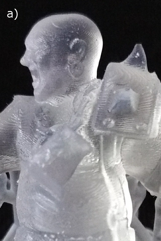
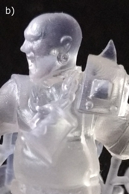
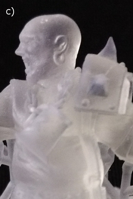
Figure 5. Photographs showing differences in figures printed with a) 0.1 mm b) 0.050 mm c) 0.025 mm layer depths.
As a conclusion the quality of the prints produced with the Form 2 printers using smaller layer depths (0.05 mm and 0.025 mm) was outstanding. We experienced no malfunctions with the operation of the device nor failed prints. The printer facilitates creation of excellent quality miniatures fit for mould making. A negative point compared to the previously tested FFF printers is the messiness associated with the resin, i.e. dedicated facilities are needed to clean up the prints. It was somewhat surprising that at the time we made the figure there were no devices available for taking care of the isopropanol washing and UV curing by FormLabs. However this has changed now and the company is selling dedicated systems also for these tasks. One of the main obstacles in using these desktop printers in mass production is still the relatively long printing times but the printers are going to get more efficient generation by generation. The printing times were similar compared to the ones with FFF printers that was a bit surprising. Laser curing of a single layer was fast, but the up and down moving of the printing plate between each layer took most of the total printing time. An additional reason not to use thermoplastic materials in this project was that PLA and ABS materials would probably not have survived the mould making process because the masters have to sustain relatively high temperatures and pressures in the process. The clear standard resin used to print the figure, on the other hand, endured these harsh conditions well and we managed to get the ordered metal casts just in time before the tournament. Finally and most importantly, it was nice that the miniature seemed to be a pleasant surprise for the tournament organizers and players.