3D scanning and printing a video game character
By Heidi Salo and Lassi Warsta AUGUST 12, 2016
We wanted to produce a 3D printed model of the worlds perhaps most famous plumber as a special house warming party gift. Instead of designing a new version of the character, we attempted to recreate an existing toy representing the popular video game character (Fig. 1a). The toy was acquired accompanied with a kids meal from a fast food restaurant in 2015. The character is depicted as running on a round pedestal covered with tiles. The 3D model derived from the toy was modified by scaling it by 300%, removing obvious features not belonging to the character, such as screw holes and spring mechanisms in the pedestal, and applying a custom ”disco” colour scheme instead of the original coloration. The objectives of the project were to test how difficult it is to reproduce an existing design in a larger format, try out 3D scanning with the MakerBot Digitizer, test a legacy 3D Touch 3D printer, and compare The Army Makers acrylic paints to previously tested Citadel acrylic paints. Also, different power tools were tested in cleaning up and assembling the model, and varnishes were used to create matt and glossy areas on the finished model.
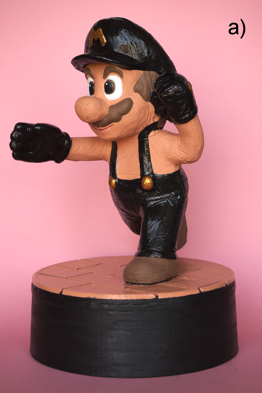
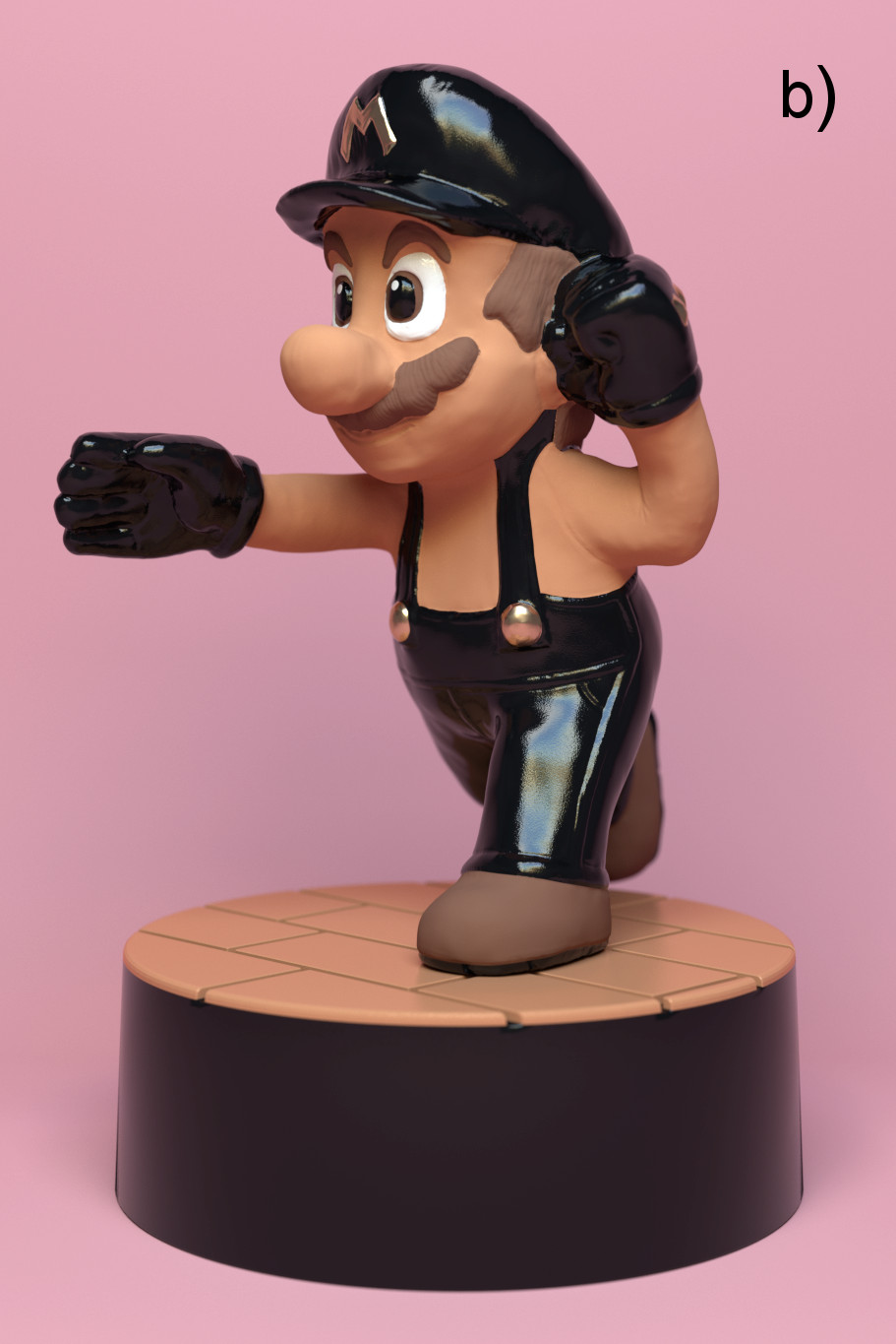
Figure 1. a) Photograph (by Tiia Lehtinen) of the printed and painted model and b) color study of the character rendered in the Blender software. Right click on the image and select View Image for a larger version.
3D scanner called Digitizer produced by MakerBot was used to digitally capture the toy (Fig. 2a). The Digitizer was available for use for free in the Kirjasto 10 library in the Helsinki city centre. The library staff introduced the system to us and were helpful with questions regarding the operation of the device. The Digitizer is composed of a round rotating tray (diameter 203 mm) and integrated lasers and a camera that capture the model from different angles. The lateral size of the scanned model has to be at least 5×5 cm2 and smaller than 20×20 cm2. The system is controlled by the MakerWare program. The Digitizer was covered by a translucent white hood to apparently shield the scanning operations from the busy library background. The Digitizer should be calibrated with a special Calibration Tool, which resembled a 90º corner with checker textures, but we were unable to conduct the procedure due to a software error in MakerWare program and this might have decreased the quality of the scan. Three different settings were available for objects with different surface properties (Light, Medium and Dark/Difficult to Scan). The original toy was glossy and it had several colours including white, red and pink, and we assumed that the third option was best suited to it. The toy was captured in three different positions: upright and on its sides to ensure that the device was able to scan the toy from every angle. A single scan took approximately 10 min. The MakerWare program automatically integrated the separate scans, created a 3D model (91 782 triangles) from the scanned point cloud and exported the 3D model into a binary STL file.
The STL file containing the scanned model was first imported into the open source and free Blender 3D modelling software (v.2.7) and then exported in obj format into open source and free Instant Field Aligned Meshes program, which was used to automatically retopologize the scanned model. The program smartly overlays a new organized mesh over the imported irregular triangular mesh that follows the contours of the imported mesh. The user can interactively fine tune the direction of the edge flow with different tools in the user interface. Currently the resulting mesh has a relatively uniform mesh density and it is apparently not possible to increase mesh resolution in user defined locations. The quad based retopologized model was exported from the Instant Meshes program in obj format and imported into Blender. The model was then subdivided four times with the Multiresolution modifier resulting into a model with 1 969 459 quads. The details in the original toy, lost in the scanning process, were manually sculpted to the model with an old Wacom Intuous 1 pressure sensitive drawing tablet. Similar sculpting methods were used like in the previous projects except that the model was not carved hollow for printing. A colour study of the model was rendered with the Cycles renderer in Blender (Fig. 1b).
Figure 2. a) Scanning they toy with the MakerBot Digitizer and b) printing the top part of the pedestal with the 3D Touch printer.
A 3D printer called 3D Touch was applied in the 3D printing process. The 3D Touch printer was originally manufactured by a company called Bits From Bytes. The company was later bought by a company called 3D Systems, who are also producing other desktop and professional printers. The printer unit applied here was initially bought by the Fablab, which is an open-access digital fabrication lab in the Aalto University in Finland, and later transferred to Aalto Ventures Program facilities. This was very convenient to us because we were sitting in the same building and the laboratory was willing to let us use the printer for free. The 3D Touch printer applies the fused filament fabrication (FFF) technology with thermoplastic extrusion. The printer can print at least ABS and PLA filaments. The printer version we were using had three nozzles (fixed related to each other) allowing the installation of three different filaments at the same time. The middle nozzle of the printer was used to print all the parts in the project.
The character model was cut down to 20 separately printed parts (Fig. 3a). The actual character was divided into 16 parts and the pedestal into four parts. The STL-files describing the parts were transformed into print instruction files for the 3D Touch printer with the Axon 2 (version 3.0 alpha 3) software. The software was easy to install into the Windows 7 operating system and to use albeit it had somewhat limited functionality compared to the CURA program used to operate the Ultimaker 2 printers. The software gave a reliable estimate for the printing time based on the print configurations for the layer thickness, position on the build plate and applied support structure type. The fill rate, i.e. thickness of the lattice inside the print outlines, of the print was approximately 10% and we were unable to change this in Axon 2. Another built-in configuration that came with the software was the raft/brim option that helped the print to stick to the build plate. The raft was composed of four layers and the print area of the raft was approximately 1 cm wider compared to the contours of the actual print. The pedestal parts were printed first with a 0.5 mm layer thickness, while the character parts were printed using a 0.25 mm layer thickness. We did not test the best print quality (0.125 mm) as the model was relatively large. The side walls of the pedestal was the largest printed part and it took nearly seven hours to print. The total print time was nearly 51 h and approximately 85 m (670 g) of PLA filament was used for the model.
The use of the legacy printer was not always straightforward or easy. A plastic tube in the 3D Touch printer was initially used to feed the PLA filament to the printing node. During a pause, the filament had spontaneously fragmented into small pieces inside the plastic tube clogging the tube. To bypass this problem, a custom filament holder was designed and built on the top of the left corner of the printer enabling the filament reel to spin during the printing process. This worked as long as the filament was neatly rolled around the reel, but overlapping of the filament on the reel often stopped the material feed and ruined the part. This occurred at least ten times during the project. Also, during several occasions we witnessed the printer shutting down when we accidentally touched moving metal parts of the printer or the protruding USB stick, used to transfer the print files from a computer to the printer. After shutdown, the printing process usually had to be restarted. With the Ultimaker 2 printers we had the pleasure to work with a heated printing bed system. The 3D Touch did not have this feature causing problems as the printed parts did not adhere well to the build plate. Especially the right sides of the parts suffered from corners rising up from the build plate because the parts were apparently cooling down too quickly. We tried to solve this problem with custom heating approaches such as using a blow dryer at the beginning of the printing process and installing an incandescent light bulb at the top of the printer. However, the use of blow dryer was too laborious, while the light bulb did not produce enough heat to help with the problem. Instead, we were able to prevent the corners from rising up by using double sided tape (Scotch double sided tape, 2.49 € inc. VAT). The tape was installed on the build plate at the outer borders of the raft of the printed part.
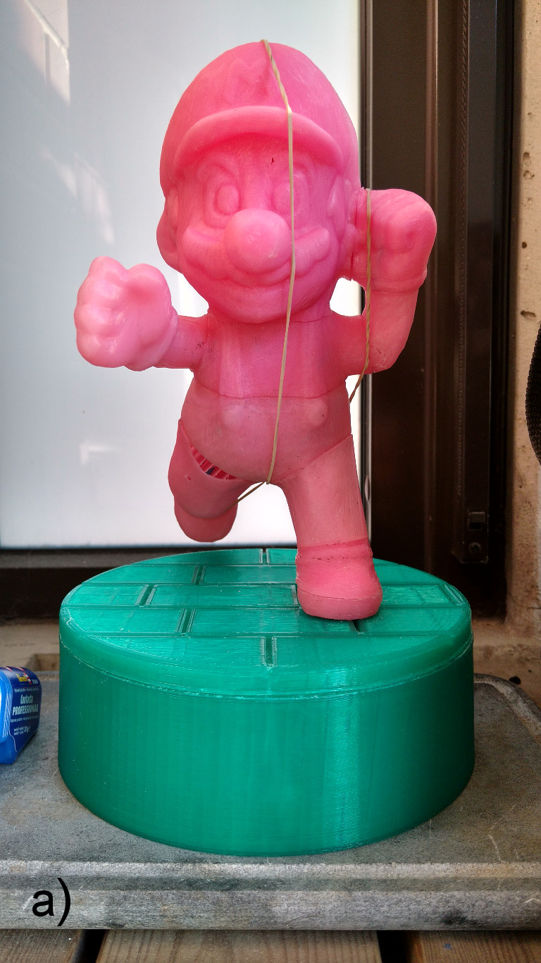
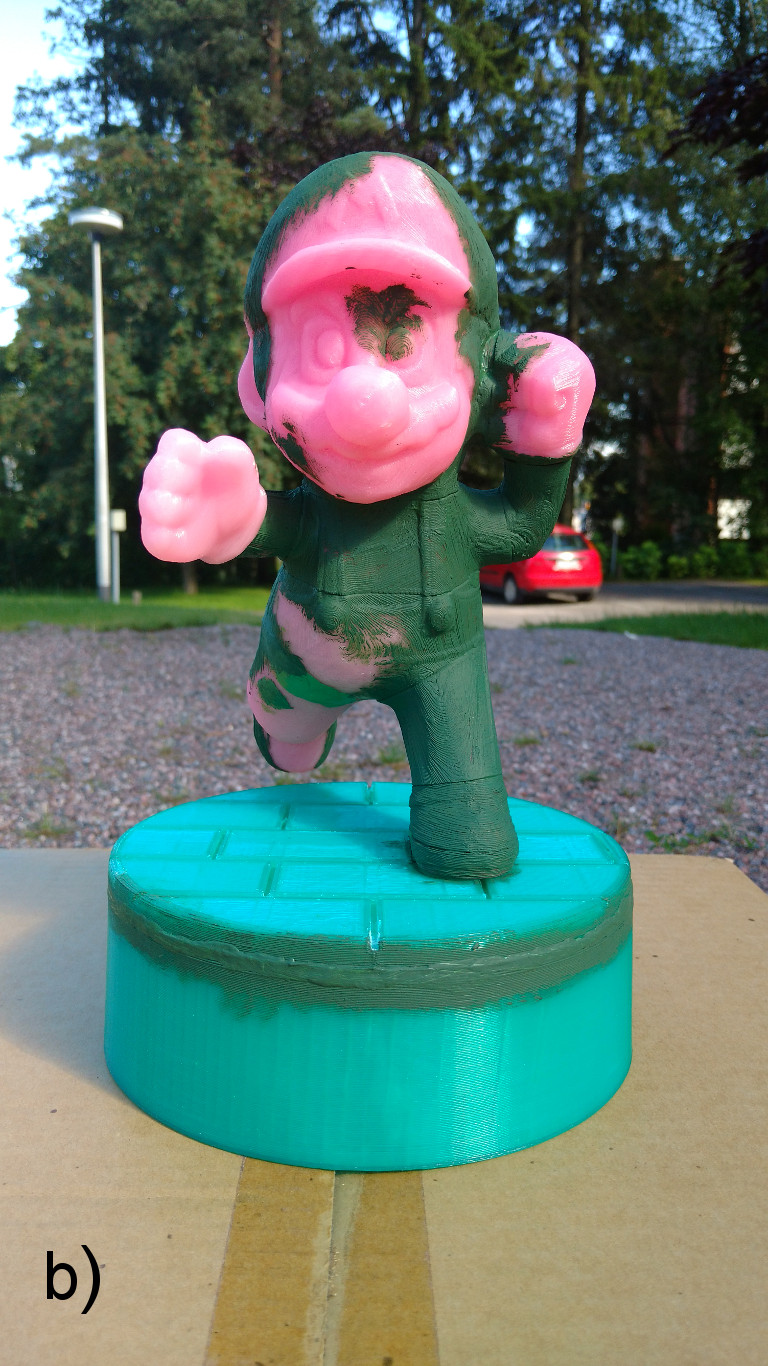
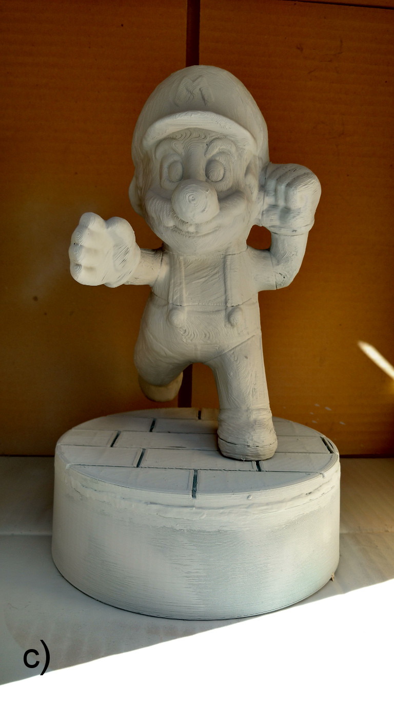
Figure 3. Pictures from different stages of the project. a) Assembled and glued model, b) model after filling the gaps between the parts and c) base painted model.
The printed parts were sanded clean with the Power Line Sanding Mouse with P60 and P80 sandpapers and the Power Craft Multi Grinder power tools. Holes were drilled with DeWalt DWD112S electric drill. The drill bits were from DeWalt DT0109 tool kit and they were originally meant for metal and wood. One 3 mm drill bit (meant for metal) was broken in the process. The holes were drilled because we wanted to use pins in the joints between the parts to make the junctions more durable. The pins were cut from the same PLA filament that was used for the printing. A 10 mm hole was drilled to the bottom of the left shoe to fit a larger pin between the character and the pedestal. Acrylic rod (from ETRA.fi) with an outer diameter of 10 mm and an inner diameter of 6 mm was used to attach the character to the base. We used plastic glue (Revell Contacta Professional) to attach the pins to the holes and parts to each other. The gluing was done in three separate sessions as the joints needed to dry before we could proceed with the assembly. For example the upper and lower body parts were glued separately and they had to dry before we could combine them. We used rubber bands to hold the glued parts tightly together as the plastic glue took some time to dry (Fig. 3a). After gluing the gaps between the parts were filled with Citadel Technical Liquid Green Stuff and The Kneadatite Green Stuff. The green stuff was found useful with filling larger holes and gaps between the parts (for example there was a larger hole between the right leg and lower front body parts) (Fig. 3b). Otherwise the liquid green stuff was easier to handle and spread on the model.
Some left over materials related to painting were available from the previous project including a can of Citadel Corax White Spray, pots of Citadel Abbaddon Black and Khorne Red Base Paints, a pot of Citadel Technical ‘Ardcoat varnish and a Citadel Base brush (L). Another Base Brush (L) (6.5 €) was bought to enable two persons to simultaneously paint the large model. All the prices reported here include VAT (Table 1). The assembled and fixed model was first undercoated with the Corax White Spray (three layers) (Fig. 3c). Instead of using Citadel acrylic paints we tested out The Army Makers acrylic paints. The pots were slightly larger (18 ml vs. 12 ml) than the previously tested Citadel versions and cost less (3.3 € vs. 2.5 €) so they were certainly more economic. The pink parts of the model including skin of the character and the tiles in the pedestal were painted with The Army Makers Barbarian Flesh Paint (see Fig. 4). The pupils of the eyes, trousers, cap, gloves and shoe soles of the character and the base around the tiles were painted with the Abbaddon Black. The irises of the eyes, moustache, hair and shoes of the character were painted with The Army Makers Leather Brown Paint. The Army Makers Greedy Gold Paint was used to put some sparkle on the M letter on the cap, knuckle emblems and jumpsuit suspender buttons. The Army Makers Matt White Paint was used on the eye balls, and the mouth line was subtly highlighted with the Khorne Red. Finally, the black and gold parts of the model and the top of the pedestal were given two coats of 'Ardcoat varnish to make them glisten, while other parts of the model were coated with The Army Makers Anti Shine Varnish to make them appear matt.
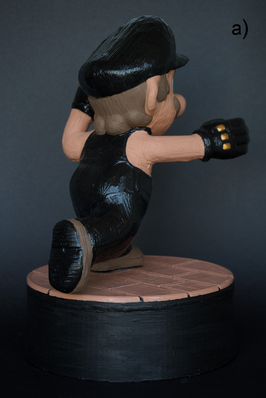
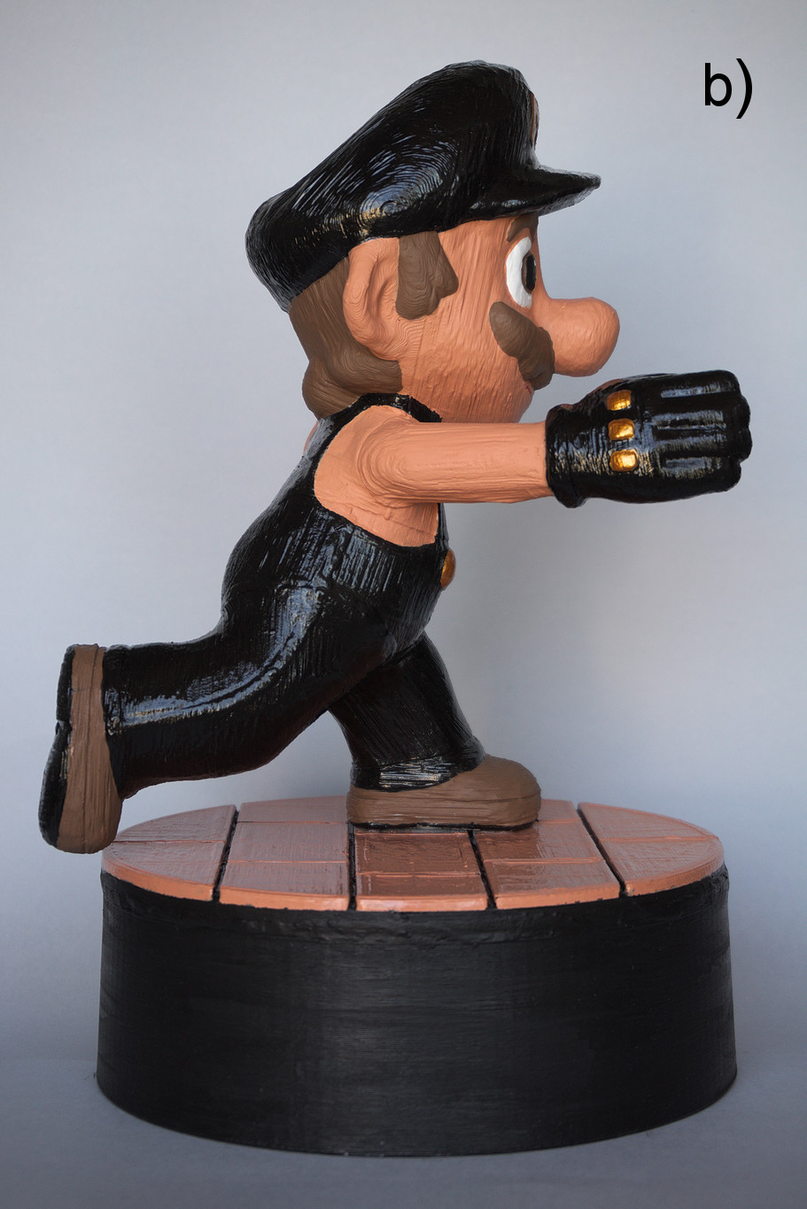
Figure 4. Photographs (by Tiia Lehtinen) of the printed and painted model from a) backside and b) side. Right click on the image and select View Image for a larger version.
We recommend that the filament feeding in the 3D Touch printer is tested by manually warming the nozzle and feeding material into the node. If the nozzle is able to cool down before the part is printed, there might be some hardened filament left clogging the nozzle. The raft turned out to be difficult to remove from the finished print. A raft made out of ABS, which is softer compared to PLA, could have been easier to remove. In the Axon 2 print configurations there was a section to define the material used for the support structures (raft) and the actual print. When breaking a 3D model into several printable parts, it is advisable to model the supporting pin holes in the parts before printing. This ensures that the pin hole locations between parts are in correct positions. While the Power Line Sanding Mouse and Power Craft Multi Grinder tools made it considerably easier to remove extra PLA from the printed parts, we recommend to use extra care when working with power tools and to use a respiration mask when sanding PLA plastic parts to prevent inhalation of the dust. Custom heated bed systems have been installed to 3D Touch printers by users and it used to be possible (edited) to buy such systems also from third party manufacturers, e.g. by GRM Products. While the results produced by the MakerBot Digitizer were not top quality, the scan helped us to define the volume of the object correctly and Instant Field Aligned Meshes program was able to produce a rather good base mesh from the scan for sculpting in Blender. In the future, it would be interesting to test advanced systems like a HP 3D Scanner (edited) to capture objects. The Army Painters acrylic paints were considerably cheaper than the Citadel versions (see Table 1 for project costs) and were of high quality and as easy to use. The unevenness visible on the surface of the printed model was caused by the printing process and not due to input geometry nor paints or varnishes.
Table 1. Breakdown of the costs for the project. Only the products that were actually bought for this project are listed below and left over products from previous projects are not shown. VAT included in the prices.
| Product: | Cost (€): |
|---|---|
| Scotch double sided tape | 2.49 |
| Citadel Technical Liquid Green Stuff | 5.0 |
| Kneadatite Green Stuff (21 cmm) | 7.0 |
| Acrylic rod (10/6 mm outer/inner radius) including a cutting fee | 3.8 |
| Citadel Base brush (L) | 6.5 |
| The Army Makers Leather Brown Paint | 2.5 |
| The Army Makers Matt White Paint | 2.5 |
| The Army Makers Barbarian Flesh Paint | 2.5 |
| The Army Makers Greedy Gold Paint | 2.5 |
| The Army Makers Anti Shine Varnish | 2.5 |
| Citadel Abaddon Black base paint | 3.3 |
| Sum: | 40.59 |